 Modii is a portal that functions as a one-way street. In only four months time we, as a group of 9 students from different faculties, designed, build and improved this interactive installation to be exposed in the hall of the Industrial design faculty of TU Delft. With the help of 20 photo’s we will tell you about our process; what went well, what went wrong and what is still to be done.
Students: Samuel Austin, Pim Glastra van Loon, Jesse Hoeksema, Meltem Kanatlarli, Daan Muilkens, Niels Stamhuis, Deniz Uygur, Thijs van der Lely, Bas Vermeulen, Tiwanee van der Horst.
Coaches: Aadjan van der Helm, Joost Broekens, Chris Kievid, Walter Aprile
Modii’s initial design was to keep the amount of visitors of the two other installations in Baai2 balanced; it distributes people to one of the other the installation that requires interaction. Modii is equipped with four interactive primitive ‘organisms’ that follow up on each other. The installation draws attention to lure you in. Therefore the first ‘organism’ has a very open personality. With the lowest interaction it will open up for you. The second module will turn on, it is more fun and interested in keeping you in. A third one will try to point you to the way out and the last will provide you with a reason to move on to the next installation.
The modularity of the doorway contributes to it’s function; the larger amount of people it will have to transport from left to right and vice versa, the larger the doorway will have to be. A parametric design was made in Grasshopper to fulfill this modularity, so that with only one mouse click another shape is created.
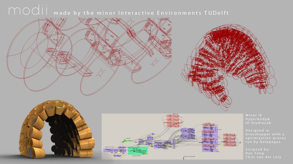
After 3 weeks of die-hard grasshopper scripting it seems that Han Feng and Thijs van der Lely have managed to finish their CAD geometry.
The pavilion geometry consists of 96 cones. Each cone contains 2 cross-sectional construction rings, 192 in total. Where these cones meet each other 422 ribs are put in place. Again, these ribs consist of multiple parts adding up to a total of 1688 components, just to create the connections.
The scripting was done in Grasshopper 0.8.0062 and 0.8.0063 with the use of Daniel Picker’s Kangaroo tool as a circle packer and with the help of Han Feng to make perfect connections for fabrication.
With the help of Grasshopper’s Galapagus tool an optimization was run to create a perfect balance of material efficiency and construction stability.
Overall aesthetic design and construction detail scripting was done by Thijs van der Lely with a helping had of Han for Grasshopper problem solving.
 What you see in the picture above, is one of the many ribs which needed to be laser cutted out of 4 mm hardwood triplex. Because of the size of the lasercutter, we used plates of 60 * 30 cm. Our first plan was to use another, smaller laser cutter. Later on, this intended laser cutter wasn’t available, so we had to change plans. The wood was already sawed for de dimensions of the unavailable laser cutter, so we couldn’t use the full size of this new lasercutter.
In the end this wasn’t much of a problem because the wood was bending and working a lot. So if these plates would have been larger, this effect would have occurred much more. With the size of 30*60 cm’s, we already had to spray them with a water spray gun on the convex surface, in order to get the plates more straight to lie on de flat surface of the laser cutter. This is very important for the result of your lasered product. The laser in the machine has a focus on a specific height. So depending on your material thickness you can move the surface on which your material is laid a bit up and down to make sure the focus of the laser is exactly in de middle of your material. If you do this right, clean cuts are made, you don’t have to go over your material a second time so this saves you a lot of time. Off course one would understand that when your material is bended a little, this effect doesn’t work out quite fine.
So when the material is laid in properly and the laser is focussed on the material, you only need to upload your autocad drawing via the laser cutters print driver and wait for some time and watch closely if everything is going right. It takes some experience before you know the exact right settings for your material. In the beginning we had to go over the material two or three times, in the end only one. In total we had to print 422 ribs, each rib containing 2 hardwood triplex sub-ribs. With an average of 8 of these sub ribs per sheet, and 25 minutes per sheet, one could imagine there is quite some time and material invested in this installation.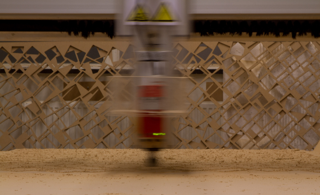
Another time intensive job. What you see here is the milling machine working on one part of the ribs. As said before, every ribs consists of 2 hardwood triplex plates (4mm) and also 4 little plates of MDF wood (6mm) these are respectively the so called outer and inner ribs. Since we had 422 and every rib containing 4 inner ribs, again one can imagine the amount of work. We used 7 plates of 244*122 cm mdf 6 mm plates. Luckily enough this is a standard machine and factory size, so we didn’t had to do any preparation work for this part of the production. It took the milling machine around 3 hours per plate to finish. Afterwards the plate had to be cleaned with a vacuum cleaner, every part tagged with a code from the computer model and then put into boxes and brought back to the science centre where it would be assembled. We used the second week of the Christmas vacation to mill and laser from 7 Am to 10 Pm, 15 hours a day!
After the inner ribs, we had to mill the inner and outer circles as well. This can be seen in the next picture, where the larger circle of each cone is to be called the outer circle, the smaller one the inner circle. For these circles we used 6 plates of the same 6 mm MDF wood and because of the larger shapes that had to be milled it took around 1.5 hour to finish a plate of this kind. We used Rhino Nest to calculate the ideal orientation and lay out of each plate filled with parts. We couldn’t use this for the outer triplex wood ribs, because we had to take the grain into account over which the parts would be aggravated.
Due to our planning we first milled the inner ribs, along with the lasering of the outer ribs, so they could be assembled when milling the circles, which would be added later on in the assembly process.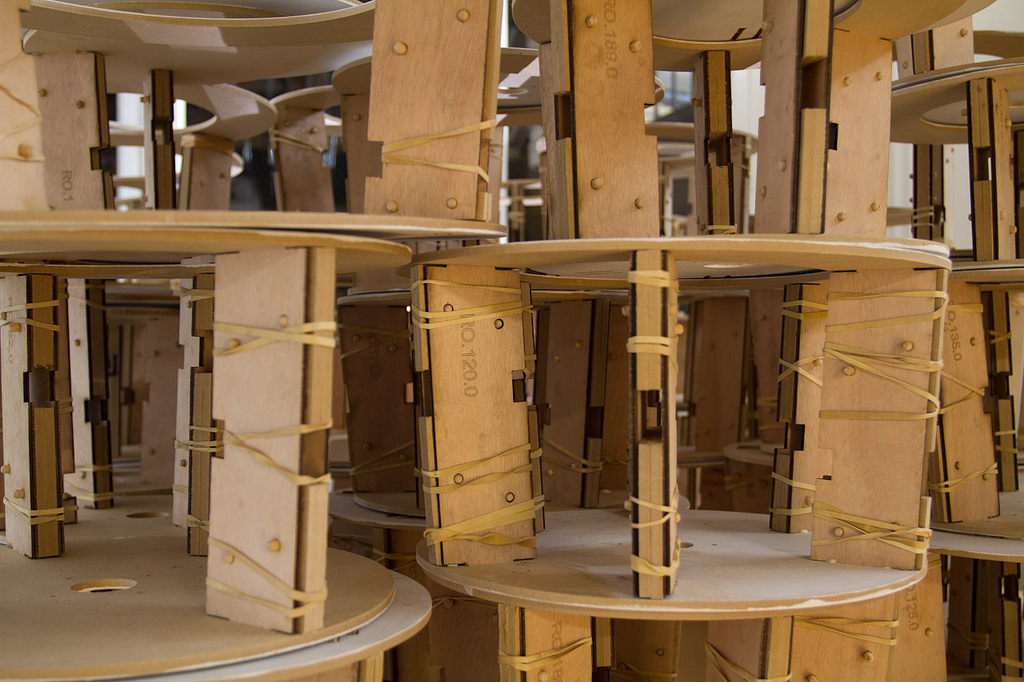
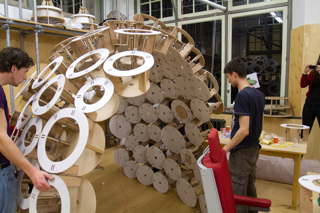
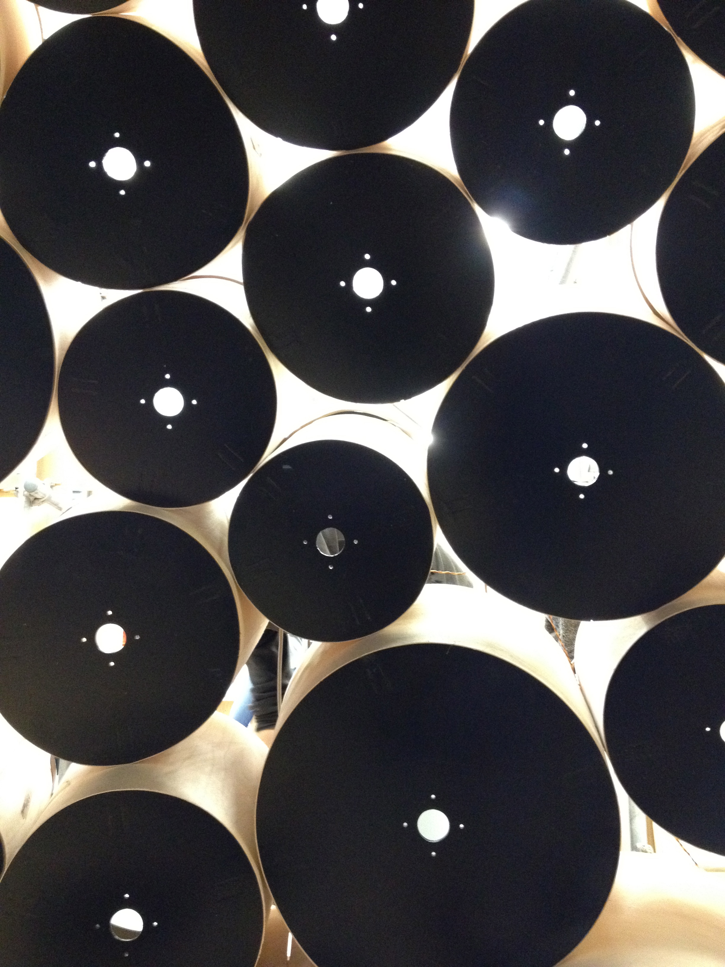
In this picture you can see a very nice view of the just described parts, all assembled into a frame of a cone. We used deuvels and glue to merge the 6 pieces of each rib together, keeping pressure on the package with some elastics. The assembling was done by 7 team members and 2 extra friends 2 days long. When all the 96 cones were assembled and stacked on to each other, we waited for the glue to be dry. When they reached this state, some of them had to be changed into a different rib coordination. Luckily enough we had our drawings from our parametric model to search for mistakes and repair them. The cones that were assembled in the right way, were then painted and laid to dry. First a layer of ground paint, and afterwards a black shiny finish on both sides of each cone.
It’s quite an astonishing look when you see the installation rising from all the individual parts. Planning in this part of the process is really essential, as well as communication. When some small tolerances weren’t taken into account, this is the moment you have to deal with these bad results. That’s why it is really important that there is always a test unit produced and assembled, before you can assume that the whole batch will be correct.
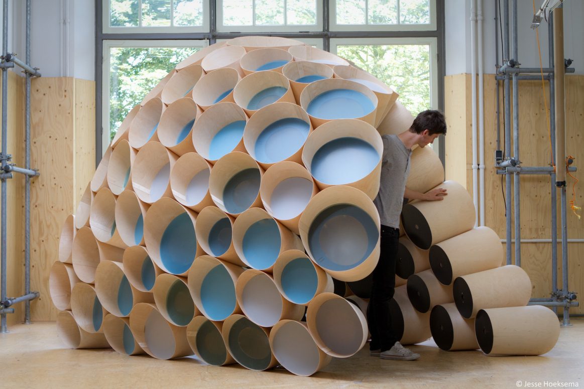
When they were all dry, we started making the cones wraps. These were made out of 0.8 mm triplex which can be bended really easily when obtaining the correct grain direction. These wraps were milled, then folded around their corresponding cone and glued together with a small rectangle of the same triplex wood. These also had to dry, so in the end we would have the cones frame and their wrap. The result is shown in the other pictures.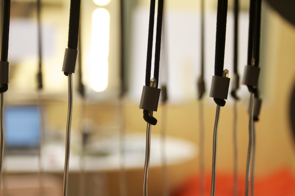
Before we painted all the cones when done assembling, we build it up entirely to test all the connections, rib configuration and strength. How a model is made in the computer can differ a lot with how it’s build in the end. For example, when set up, due to the working wood, we had a margin of around 1.5 meter between the 2 walls. The installation seemed to held it, but one knows that there will be a lot of uncalculated tensions in the material when de model isn’t placed correctly. That is why in the end we placed some silicon strips under the cones that were situated on the ground, in order to keep de walls at the right distance of each other.
Because we didn’t had the 0.8 mm triplex assembled in the first build up of the installation, we used small pieces of wood to imitate the 1.6 mm space between the cones. If this wouldn’t be done, in the roof of the installation some connections could differ around 10 cm. In order to balance the wall when it reached the covering part, we used a rope attached to the framework that was build in the interior of the Science Centre.
Another advantage of building the installation in the test phase, is that you learn a lot about it. There were some tolerances and things that weren’t foreseen while designing the model on the computer. For example, some cones were too small to stick a pen through the connection holes, some other cones broke under the pressure of the whole and had to be redesigned. Some cones only had 1 rib and were therefore very unstable. And as said before, if a configuration of a set of ribs in a cones isn’t correct, this is the moment when you acknowledge that. If we wouldn’t have done that, we would have had to re wrap the 0.8 mm triplex cones inside out, leaving very nasty glue marks on the new outside. That is also why you should always order some extra material so that you can make these mistakes and learn from them.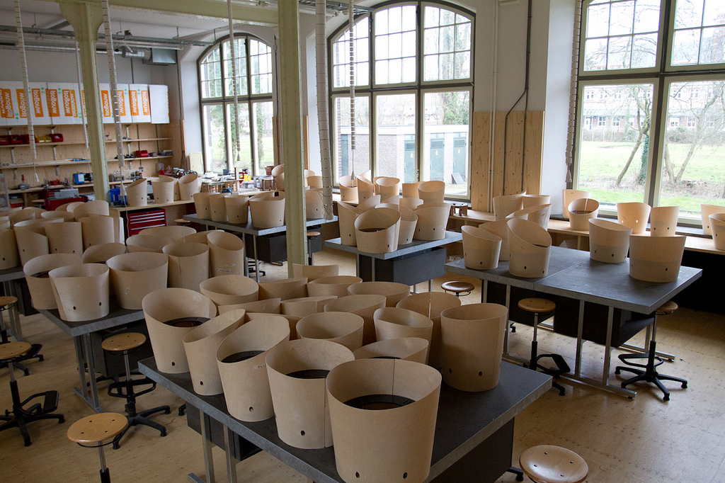
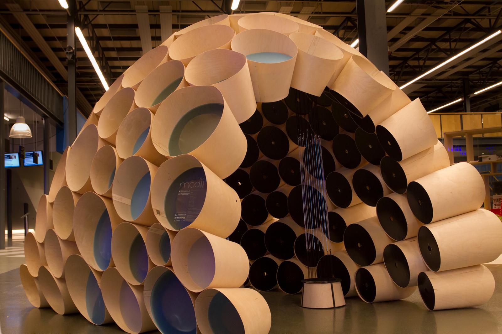
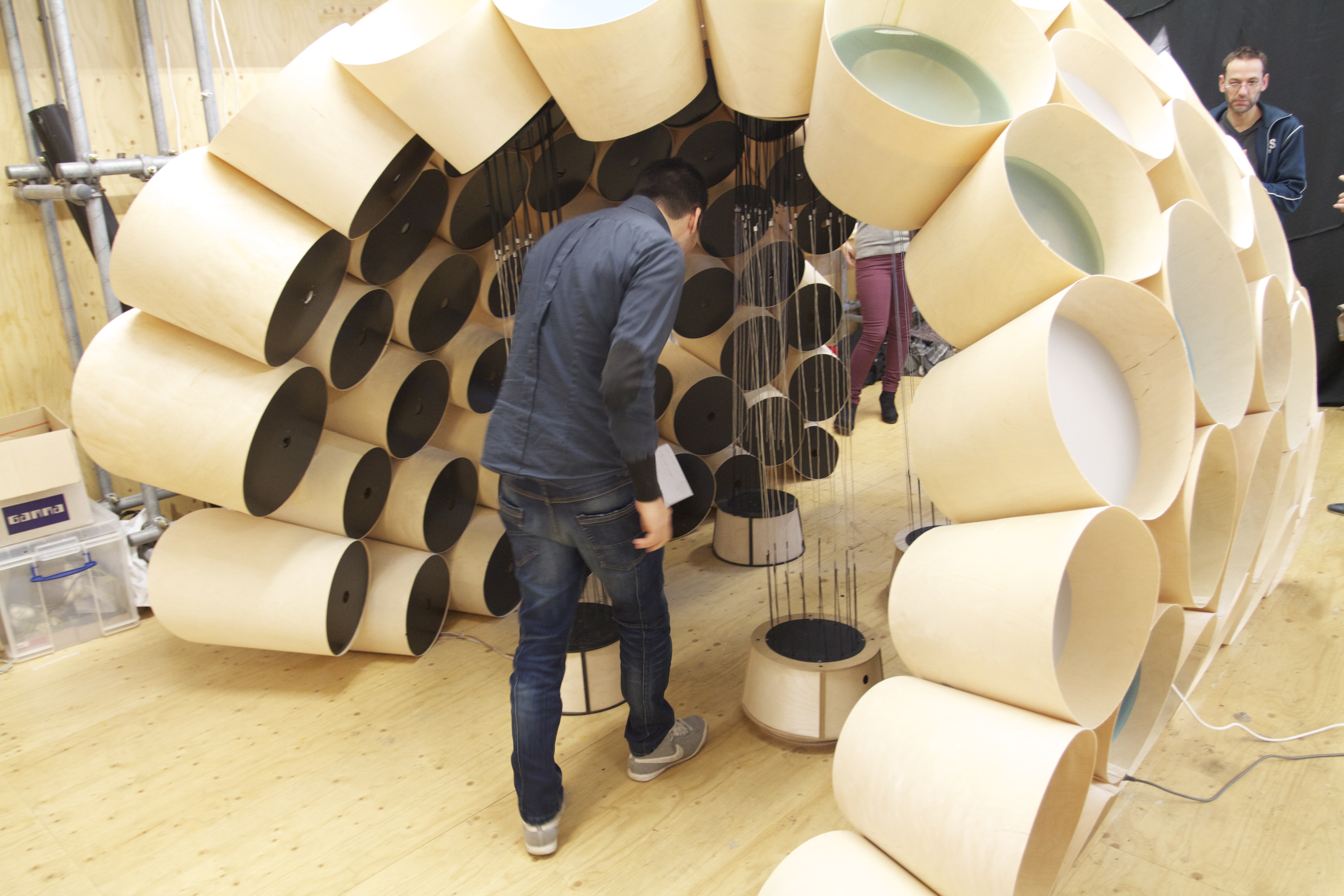
In this picture you can see all the cones assembled with their corresponding wrap around them. Now all that had to be done is the assembly of the entire installation so that the electronics could be applied. This is one of the moments where you can really enjoy your work so far and it starts to pay off in astonishing looks and feels. When all the wraps are glued the right way, the milled holes in the wraps should correspond to the holes from the ribs in the framework. As far as we were here we assumed that it was just a matter of implementing the electronics and we would be done. Unfortunately this didn’t went as we had expected.
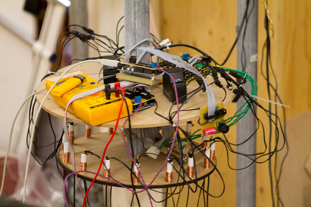
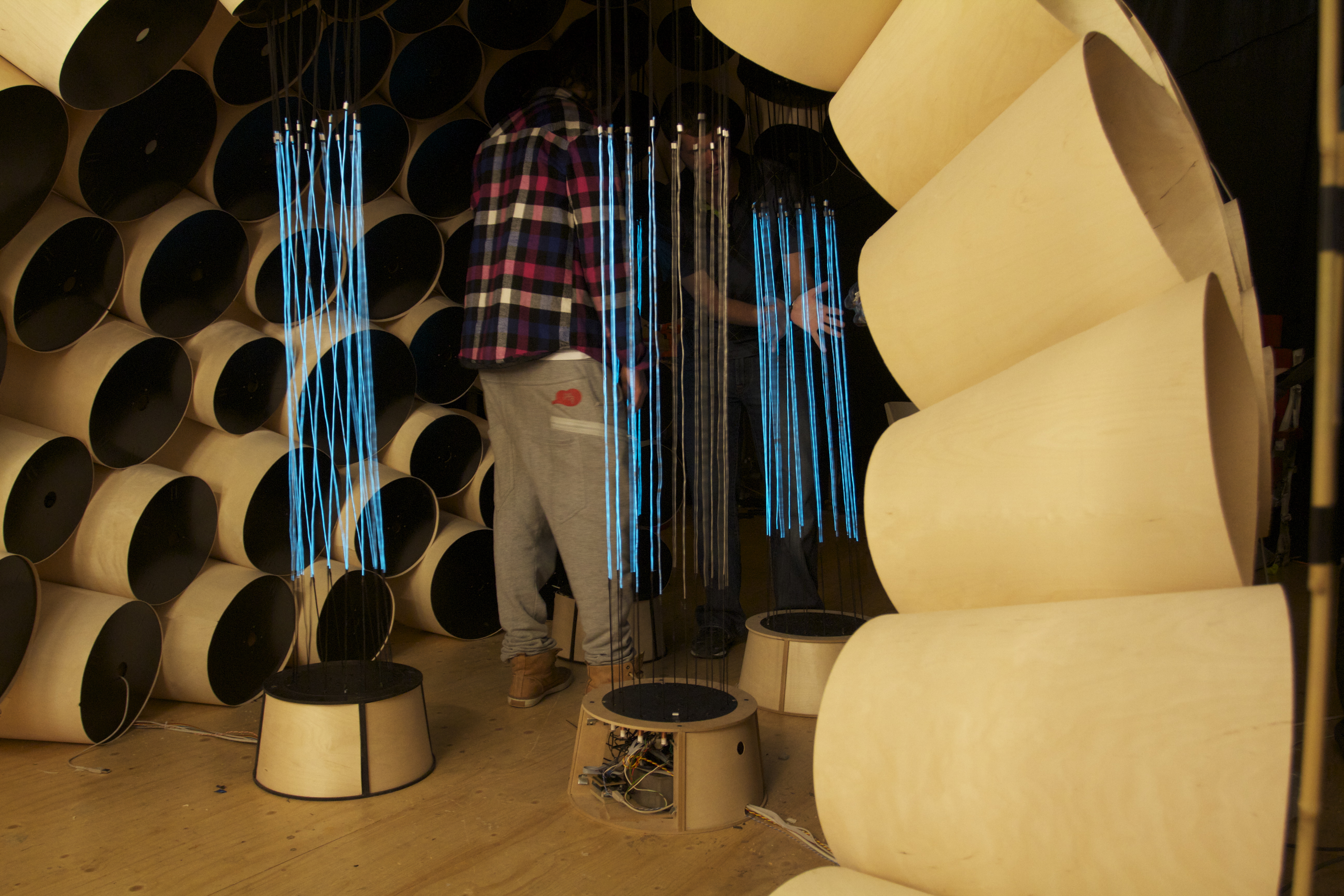
When we had built the test setting for the modules that would later one be placed in the installation, everything looked fine. Working sensors, corresponding feedback in the software and programmable thresholds for the right reactions of the motors and EL wires. When we putted al the cables through the installation in the final phase, the pulling sensors where constantly triggered, letting a module think someone is near all the time. This was very unlucky for the interaction as it wouldn’t work as expected. So our last phase was primarily about making sense of the interaction that we could manage. If we would make a version 2.0, a lot that was learned during the first version could be used.
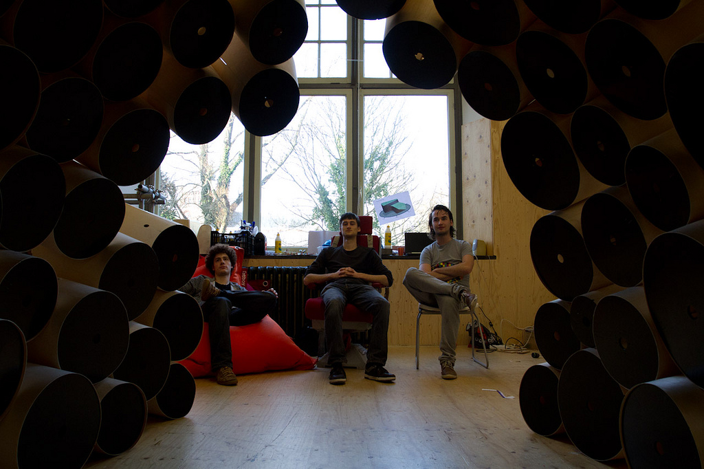
For example, the cones work as a sound reflection box, unintended. When you use ultra sound sensors to detect a person, the readings from these sensors are very disturbed. A positive thing we did not thought of in the design was that the sounds which are produced by the motors give the entire installation a certain character. We knew that the sound would be there, but we didn’t expected it to be so dominant. It turned out that the reflective quality of the cones worked as a enforcing value for the experience of the inside of the installation which was designed as a intimate space. Now with the sounds stronger as expected, the inside became more intimate and astonishing due to the moving parts and corresponding sounds.
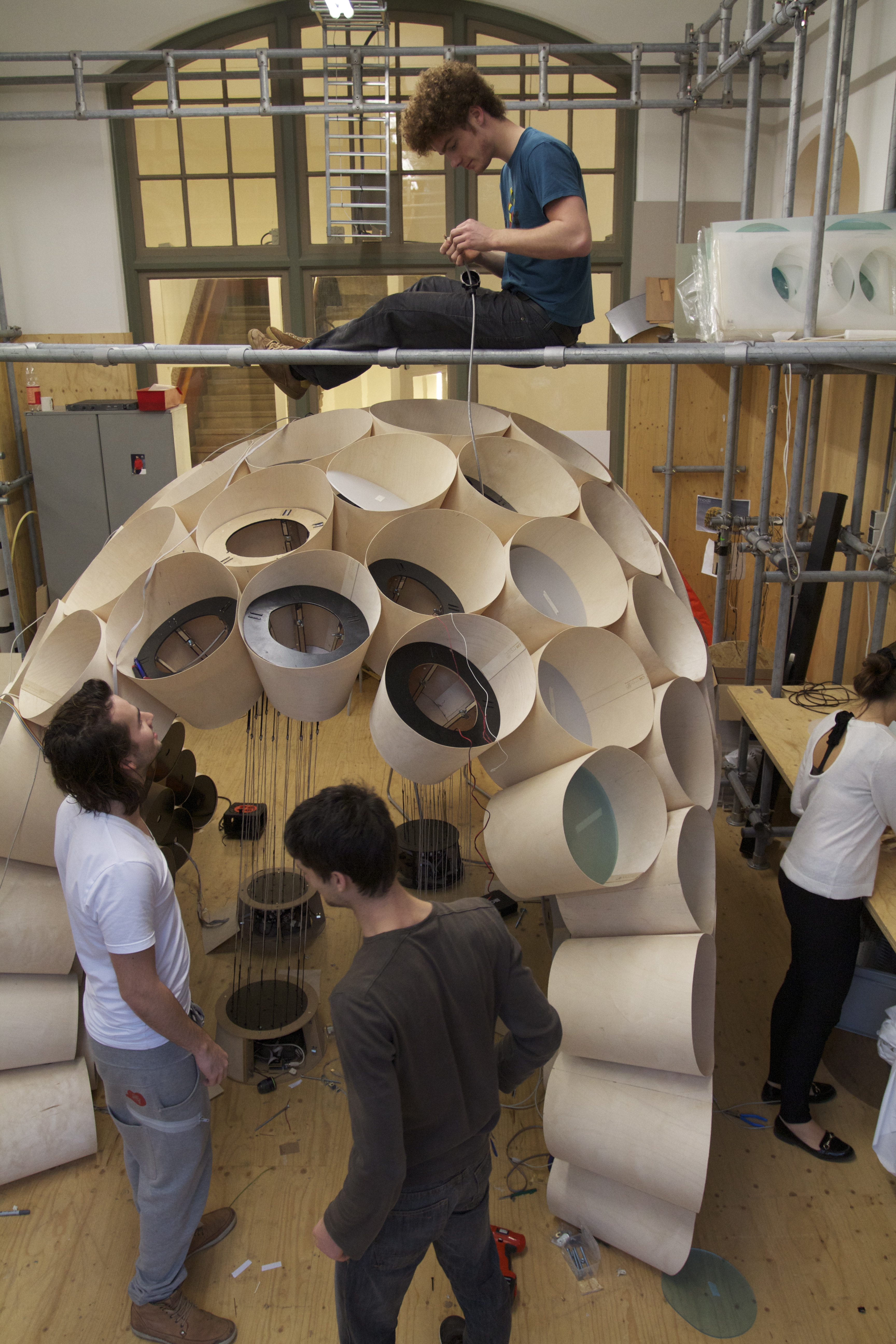
When all electronics and cables were ready to be installed we had to think of a way to reach the top of the installation. Before we came up with a plan, Jesse allready took some pipes down from the pipe rack and build his very own bridge, which came in handy because with cabling the installation hours were spent on top of it.

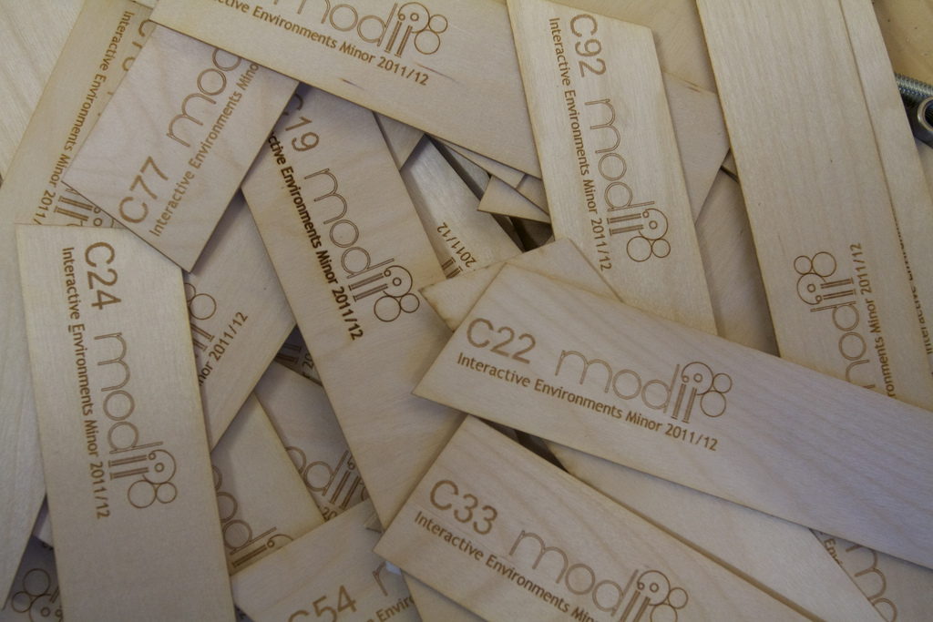
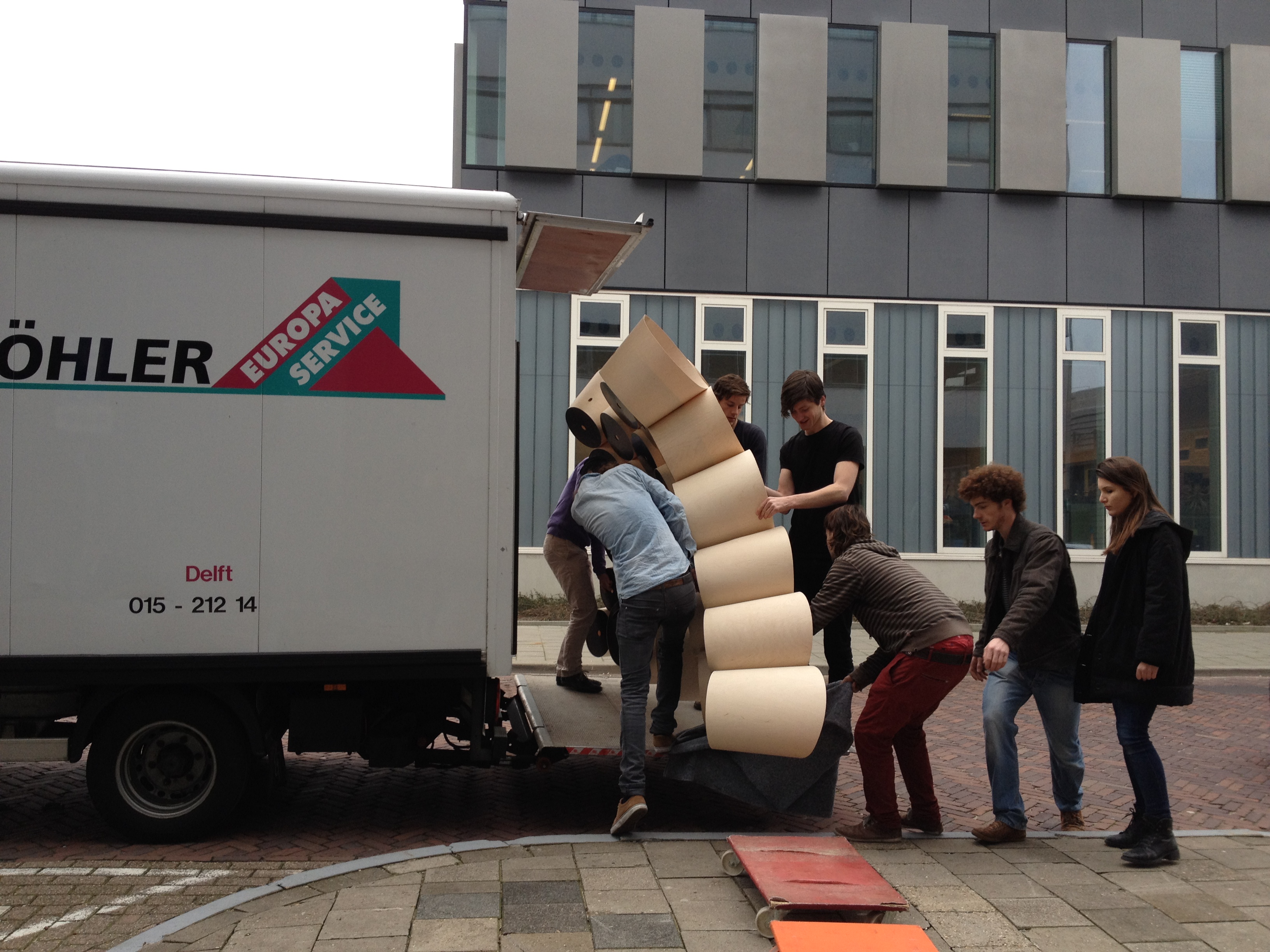
The final exposure (for the minor that is) of our installation was at the IDE faculty. We split our installation into 3 big pieces, all fully equipped with lots of electronics, but we had to be even more careful with the wrapping. We needed a day to disconnect the electronica and cones and prepare for transportation. In only two hours the installation was moved from science center to IDE, and yet another half a day was needed for building it up again. Luckily, we tagged every single piece in a structured way. So for example, we tagged the plastic plates not only per cone, but also for the way it needed to be placed.